progress: casette
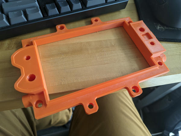
For my two-sided PCB mill, I'm designing a casette that carries the FR-1 blank. The aim is to put indexing features on the casette rather than milling them into the blank.
This solves a whole bunch of problems mechanically that otherwise would require rather more involved solutions (a vision system, milled locating pins that would require manipulation, etc.).
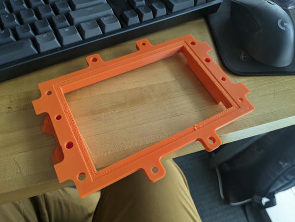
The first design (above) is a two-part carrier held together with M5 bolts and heatset inserts. The top and bottom pieces are identical and symmetrical about 180 degree flips.
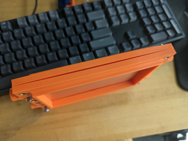
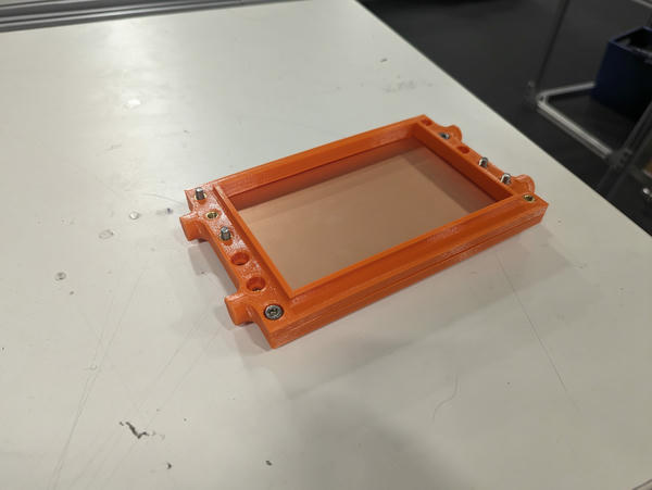
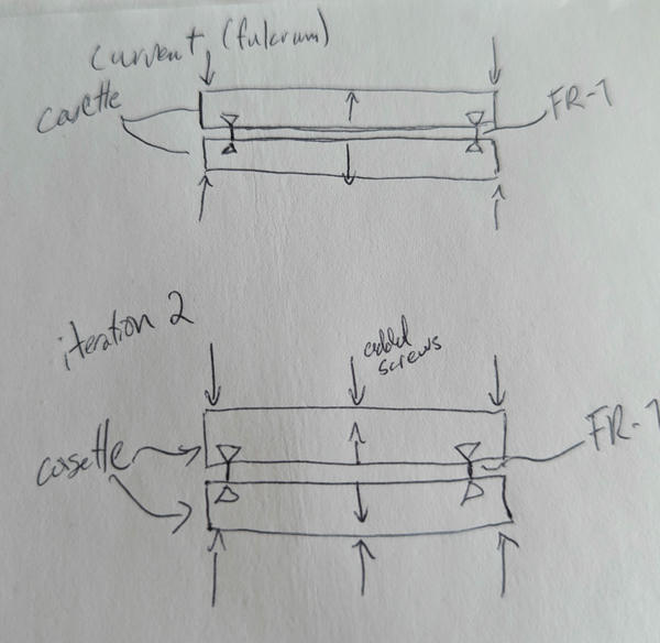
Unfortunately (and unsurprisingly) this design has a gap in the center where there is no clamping force. The second design adds bolts to apply clamping force here:
And adds the Kleat kinematic mount:
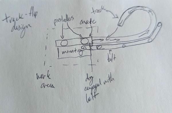
Next iteration will adjust the Kleat mounting point and pin lengths so they don't collide. I'm still solving for the interaction between the mount and the board-flipping system.
considerations: clamping force
Another way to solve the center-clamping problem would be to print the casette bowed out / as a spring that must meet in the center first and is then preloaded using the bolts on the edges.
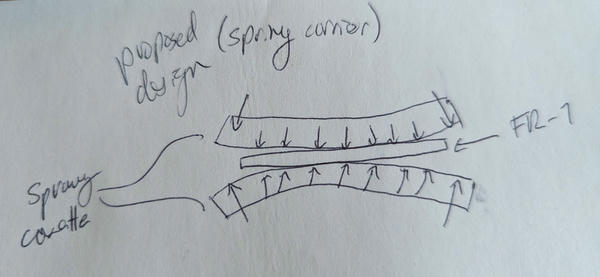
This would be nice in that it would reduce part count and presumably clamping uniformity (the current solution of additional screws along the long edges I expect has a tendency to pinch only the outside edge of the board). However, this approach would make 3d printing very annoying, as I'm using the inner face as a flat surface that doesn't require support. Additionally, I expect PLA/PETG to creep, so I would anticipate clamping force to drop off over time using this approach. Perhaps it's acceptable?
The other obvious way I can think to approach this is printing the parts flat, then heat-softening and molding them to have that slight curve. Doing this would require a jig and a heater, but might be worth it.