laser
Laser cutter: 30W GCC
Final result
settings
Using the suggested settings as a baseline, I arrived at the following refined numbers for 1/8" cardboard:
| speed | 2.3% |
|---|---|
| power | 100 |
| ppi | 220 |
The largest item causing variance in cut quality was focus -- my cardboard sheet was bowed up, causing me to lose focus in the middle of the sheet, leading to a black burn on the upper surface blooming from the cut location and loss of effective cut power. I noticed this by comparison as I was watching Cayden and Lancelot cut their projects.
kerf characterization (part 1)
I initially tried to measure kerf with arrays of interlocking fingers of increasing kerf compensations.
I measured the thickness of the cardboard using a set of calipers and found that it was approximately 4.15mm thick. The finger widths thus started at 4.15mm and increased in 0.2mm increments. I anticipated that this would make the first two indices too small, as Neil told us that the beam waist was in the ballpark of 0.010". 0.1mm is approximately 0.004", so I would have expected an interference fit between indices 2 and 3. However, index 1 fit perfectly (no kerf compensation).
I realized the error of my ways after the fact as I was building my project: the precision of my measurement was reliant on my ability to measure cardboard thickness precisely with calipers, and on cardboard having a consistent thickness in the first place. I remedied this later.
project summary (or: kerf characterization part 2)
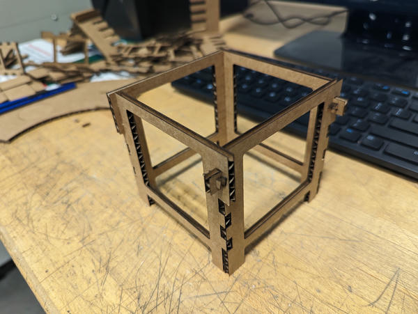
I made parametric cardboard holders. Their function is simply to elevate an object. I started out making small boxes using box-jointed edges and realized that (obviously) they would not hold with just a box joint (I'm used to using adhesive).
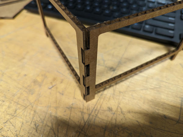
This, however, let me dial in my kerf, as the precision in the box joint is entirely in the vertical axis and not dependent on the thickness of the cardboard at all. I binary searched, printing repeated joints, and arrived at a kerf compensation of 0.15mm (= approx 0.006"), giving an interference fit inasmuch as one can be said to exist in cardboard.
wedged joints
Given that the joint was not going to hold as-is, I added a joint (topmost on the edge) that could accept a wedge.
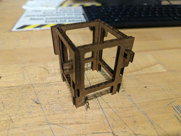
Wedges installed:
The complete support is relatively sturdy for what it is. Holding a power supply on my desk:
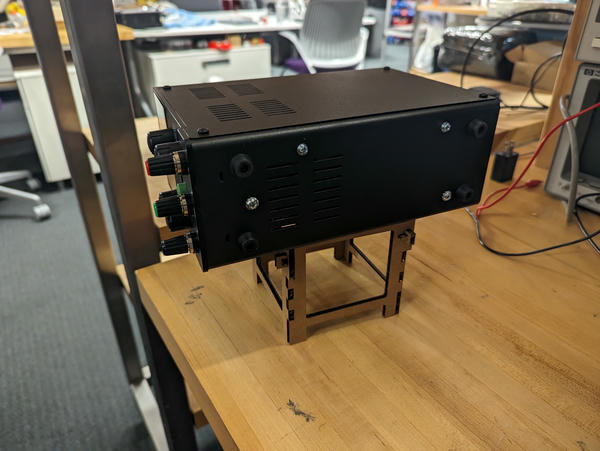
I don't believe the wedges are actually in any significant shear loading while the structure is bearing weight -- I think the increased friction of the joint as a result of this construction is actually what's providing most of the stability.
cutting wedges
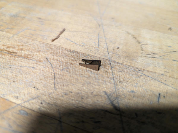
The wedges were difficult to cut, small as they were:
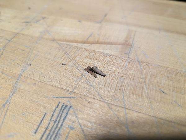
The above wedge failed because it was cut along the axis of the cardboard corrugations and could easily twist off of the single line of glue. I soon realized this and changed them to be cut across the corrugations.
I still had some failures this way due to delamination, but under 20%.
Originally, I was cutting the wedges one-by-one in left-over areas on the cardboard between the walls, but I decided to develop a way to pack them more densely.
First, I simply went for a dense packing in an array:
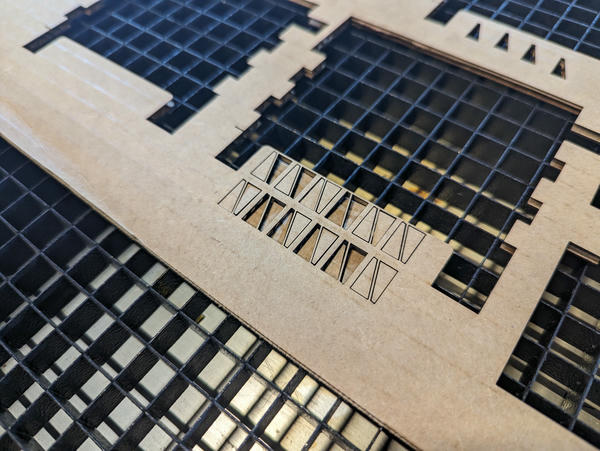
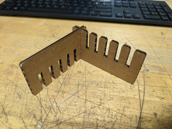
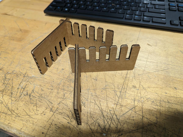
Then I built a "sprue tree" out of cardboard to retain several wedges as one complete unit that could be extracted from the laser cutter more easily.
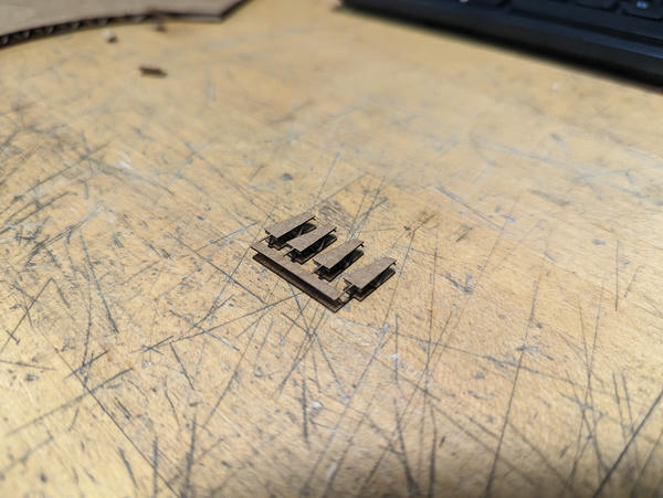
Surprisingly for how thin the connecting member is, these came out without tearing any of the "sprues" very consistenly.
parametricity
Adjustable parameters:
- Height
- Width
- Leg height
- Number of box fingers
- Cardboard thickness
The cross-member thickness is a proportion of the width or height of the relevant direction.
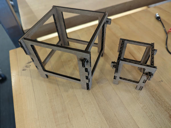
A small box and a big box patterned from the same design file:
corel draw tricks
The best way I could figure out to use Corel Draw was as follows:
- Set the "paper" as the full size of the bed
- Pick a color that is your no-cut color (I picked blue) and configure the printer not to cut it (uncheck vector, raster in the color configuration)
- Draw a rectangle within the bed outline that is the size of your cardboard (colored no-cut) as a reference
- Keep working off of this one file: each time you print a part, mark it no-cut but leave it in-place. Now you know what parts of the sheet you've used and can squeeze in other parts quite precisely.
Additional note: there is a palette of recent colors in the bottom left. Right-click a color to set the currrently-selected curve to that color (left-click is fill).
design files
Here.